ARTIFICIAL LIFT FUNDAMENTALS- Part 3
ELECTRICAL SUBMERSIBLE PUMP (ESP)
Electric submersible pump is an artificial-lift method for lifting moderate to high volumes of fluids from wellbores. The pump typically comprises several staged centrifugal pump sections that can be specifically configured to suit the production and wellbore characteristics of a given application. An electrical submersible pumping unit basically consists of an electric motor with seal section, multistage centrifugal pump with an appropriate intake section, round and/or flat power cable, motor lead extension, motor controller and power transformer. In addition to the basic equipment, depending on application, several accessories may be required, such as tubing and couplings, swage nipples; cable guards, clamps, reels and supports, check-valve, drain valve, centralizers, a down hole pressure and temperature sensing instrumentation systems, etc

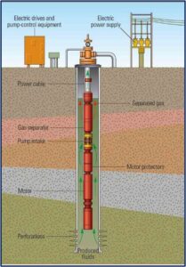
ESP System
Power passes through a cable running from the transformer to the switchboard and junction box, then to the wellhead. The motor, seal, intake and pump assembly, along with the power cable, goes in the well as the tubing is run. The well power cable is spliced to a motor cable that is connected to the outside of the downhole assembly. Below the pump is an intake that allows fluid to enter the pump. Below the intake is a gas separator and a protector or seal, which equalizes internal and external pressures and protects the motor from well fluids. At the bottom is a motor that drives the pump. The assembly is positioned in the well above the perforations; this allows fluid entering the intake to flow past the motor and cool it.
The three major types of ESP applications are:
- High water-cut wells producing fresh water or brine.
- Wells with multi-phase flow (high GOR).
- Wells producing highly viscous fluids.
Basic ESP components and their functions
The components of an ESP system can be categorized into surface and downhole equipment:
Surface Components
- Switch Board: The switchboard controls the pump motor and provides overload and underload protection. Protection against overload is needed to keep the motor windings from burning. Protection during underload is needed because low fluid flow rates will prevent adequate cooling of the motor.
- Junction Box: The junction box connects the power cable from the switchboard to the power cable from the well.
- Transformer: The Transformer system is used to step-up or step-down the voltage from the primary line to the motor of the submersible pump.
- Wellhead Feed-Through Connection: The wellhead must provide means for installing the cable with adequate seal May include adjustable chokes, bleeding valves Onshore wellheads have a rubber seal and offshore have an electric mandrel.
Downhole Components
- Pump: Electrical submersible pumps are multi-staged centrifugal pumps. Each stage consists of a rotating impeller and a stationary diffuser. The performance of the pump depends on the stage design and size, rotational speed and fluid being pumped.
- Motor: The criterion for selecting the motor with the proper power capacity is the total power requirement of the ESP system, BHPsystem, that consists of the powers needed to run (the pump, the protector, and the gas separator (if used).
- Intake/Separator: Used in applications where free gas causes interference with pump performance. Units separate some of free gas from fluid stream entering pump to improve pump’s performance.
- Cable: A power cable runs from the junction box then through the wellhead and all the way to the bottom to supply power to the pump motor. Cable is available in round and flat styles. Cable type/size selection is primarily based on fluid conditions, BHT and space limitations within the casing size.
- Seal Section: Protects motor from contamination by well fluid, absorbs thrust from pump and equalizes pressure between wellbore and motor.
ESP Design Guidelines – 9 Steps
- Basic Data: Collect and analyse all well data (production, well fluid, power sources etc) to be used.
- Well Production Capacity: Determine the production capacity and depth.
- Fluid Volume Calculations: Calculate all fluid volumes at pump intake pressure.
- Total Dynamic Head (TDH): Determine the pump’s discharge requirements.
- Pump Type: Select pump that has highest efficiency based on desired flow rate.
- Optimum Size of Components: Select optimal size of pump, motor, seal section and check the limitations if any.
- Electric Cable: Select correct type and size of cable based on well.
- Accessory and Optional Equipment: Select motor controller, transformer, tubing head and other optional equipment.
- Variable Speed Pumping System: For additional operational flexibility, select the variable speed submersible pumping system.
Advantages of ESP
- Generally considered a high-volume pump.
- They have a relatively small “surface footprint,” and so are appropriate for use in offshore, urban or other confined locations.
- Adaptable to highly deviated wells; up to horizontal but must be set in straight section.
- They are relatively simple to operate.
- They generally provide low lifting costs for high fluid volumes.
- Applicable in a range of harsh environments.
Limitations
- They require a source of high-voltage electric power.
- They are not particularly good at handling gas and solids production.
- Costly pulling operations and lost production occur when correcting downhole failures, especially in an offshore environment Fluid viscosity.
- ESPs are not particularly adaptable to rates below 150 B/D.
To Learn More about ESP Design using NODAL Analysis, attend one of the our related courses: Integrated_Production_Modelling and Artificial_Lift_Design&Production_Optimization.
Accrete can also support your integrated asset modelling projects executed to achieve defined engineering and business objectives.
| © 2021 ACCRETE PETROLEUM LIMITED
| Plot 26 A, Block 12, Jakande Crescent, Off Palace Road, Oniru Estate, Victoria Island, Lagos, Nigeria
| info@accreteltd.com +234 908 555 0001 www.accreteltd.com |
