Artificial Lift Fundamentals – Part 2
GAS LIFT
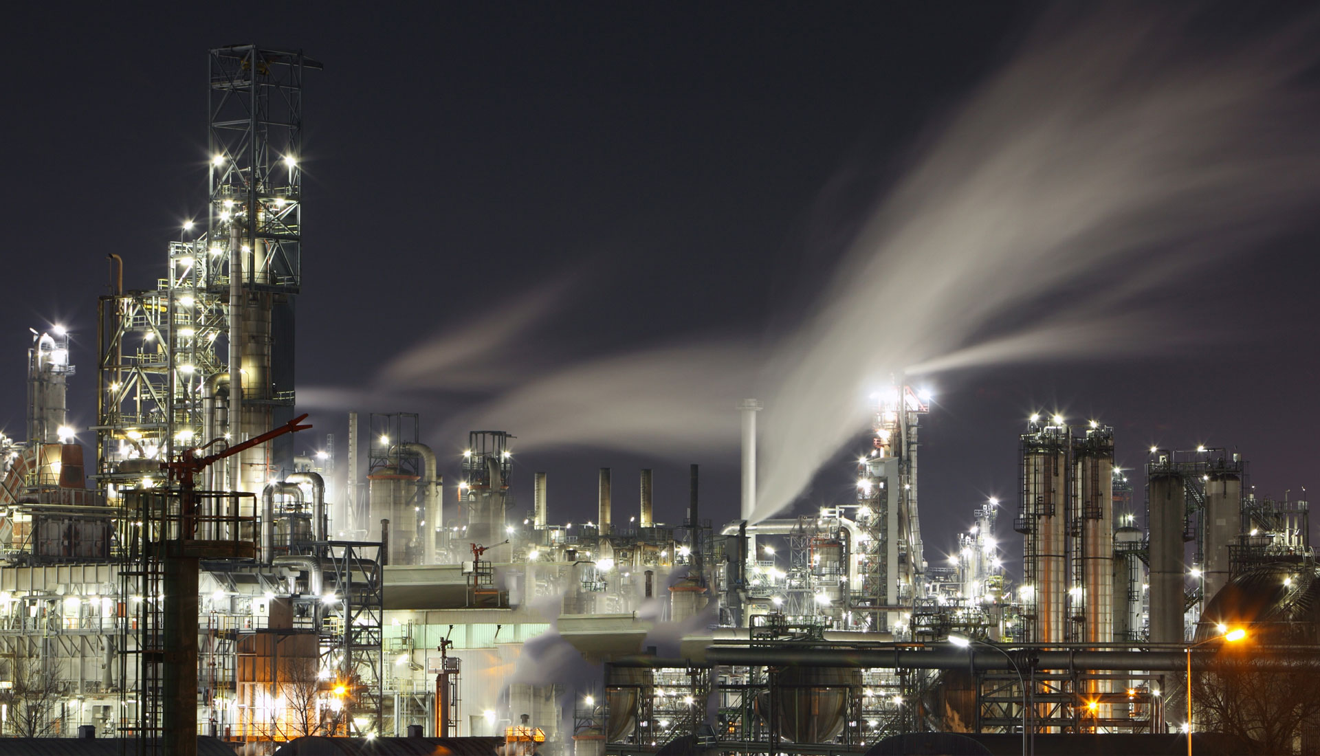
Gas lift is a process whereby liquids are ‘lifted” to surface by injecting pressurised gas into the production conduit where it commingles with the produced fluid and consequently reduces the hydrostatic head of the fluid column in the tubing. This is usually done by gas injection into the tubing from the annulus. It is particularly useful for lifting wells where a large volume of high pressure (non-corrosive) gas is available from a nearby well or field.
In the absence of an external source of gas a closed system may be used. Gas lift may be continuous or intermittent. The choice of method will depend on the flowing characteristics of the reservoir.
How Gas Lift Works
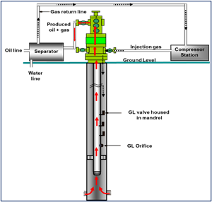
- Pressurized gas is injected at depth in the well to lighten the density of the liquid column.
- Decreases hydrostatic pressure.
- Injection is performed in stages from top to a predetermined orifice depth via gas lift valves. Thereafter injection is kept at that depth throughout the lift assisted production period.
Gas Lift Components
The following are the components of Gas Lift system and their functions:
- Gas Lift Valves: These provide down-hole control of the rate of injection and the timing. They can be fitted with a range of orifice sizes to govern the injection rate.
- Side Pocket Mandrels: A completion component that is used to house gas-lift valves and similar devices that require communication with the annulus.
- Surface Controls: These are installed on the surface to provide control for pressure regulation, injection volume and timing.
- Separation System: To separate gas from produced liquids and provide liquid and gas metering. Production flowline to separator must have minimum restriction, i.e. no chokes and separator back pressure must be as low as possible.
- Compressor: Takes gas at separator pressure and supply it at required injection pressure. In other words, add the required energy to the system.
| Advantages 1. High degree of flexibility and design rates 2. Valves are wireline retrievable 3. Handles sandy conditions well 4. Allows for full bore tubing drift surface Wellhead equipment requires minimal space 5. Multi-well production from single compressor 6. Multiple or slim hole completion | Limitations 1. Requires high-pressure gas well or compressor. 2. One well lease may be uneconomical 3. Fluid viscosity 4. Bottom hole Pressure 5. High Backpressure |
The PROSPER module of the Petex IPM suite is used for well performance design and optimization. It can model and optimize most types of well completions and artificial lifting methods. PROSPER has a robust gas lift design module and can capture transient valve performance and other transient pressure and temperature changes during the unloading process.
To Learn More about Gas Lift Design using NODAL Analysis, kindly attend one of the our related courses: Integrated_Production_Modelling and Artificial_Lift_Design&Production_Optimization.
Accrete can also support your integrated asset modelling projects executed to achieve defined engineering and business objectives.